Atkinson Tankmaster Fitting Instructions
- Remove circlip in the centre of the handle. To remove circlip hold handle away from circlip and insert screwdriver in one of the two slots in circlip (holding the screwdriver handle in the palm of the hand), slide thumb down screwdriver blade until in contact with circlip and prise off, holding circlip between thumb and screwdriver all the time.
- Turn the handle clockwise until it is removed.
- Undo the union nut.
- Push out union from body and remove ‘O’ rings.
- Dress union threads with PTFE tape and suitable pipe sealant, careful not to get tape off the end of the union. Screw union into tank boss.
- Place one ‘O’ ring on union body.
- Position gauge body over union body to suit take-off direction (the gauge body is reversible)
- Place second ‘O’ ring in position then replace and tighten union nut, making sure thread recess is next to the gauge body.
- Replace handle and circlip. To replace circlip slide the open end of the circlip into the groove and then press full home by using the flat of a screwdriver. When circlip is in position ensure that the handle is turned clockwise to leave the valve shut until you are ready to allow the fuel to flow.
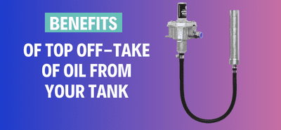
- The sight tube assembly should now be screwed into the gauge body and the thread sealed using PTFE Tape, the sight gauge should at all times, throughout it’s length, be as close to the tank as possible. The top clip is secured to the tank top by means of the two self-tapping screws provided.
- The top cap is then fitted and secured by means of one self tapping screw through the cap into the back of the sight shield.
- The oil line should now be connected using the 10mm o.d. compression fitting provided. Before fitting the oil line, insert the hard copper insert into the cut end of the 10mm o.d. soft copper line before making the compression joint. Fittings provided.
- IMPORTANT. When the tank has been filled the Sight Tube Knob should be held open until no further air bubbles pass up the sight tube. This will allow any air trapped in the filter bowl to escape ensuring free flow of oil down the feed line

4549 (6.25 inch) dependent on length required, joint between Tankmaster and Adaptor should be sealed with PTFE tape and joint between Adaptor and tank union should be sealed with PTFE tape and a suitable pipe sealant. Adaptors are available from your normal stockist.
